Few words will make a machinist swear as quickly as “sharp inside corners”.
There’s good reason for this. They’re an absolute pain, and often totally unnecessary.
Let’s go over why square inside corners face such animosity from machinists, how you can design machined components so that they won’t need these corners 99.99999999997% of the time, and what can be done when you’re facing the 0.00000000003% of occasions that actually require them.
If you want to skip straight down to the part on how to make them, then use the table of contents to navigate.
Table of Contents
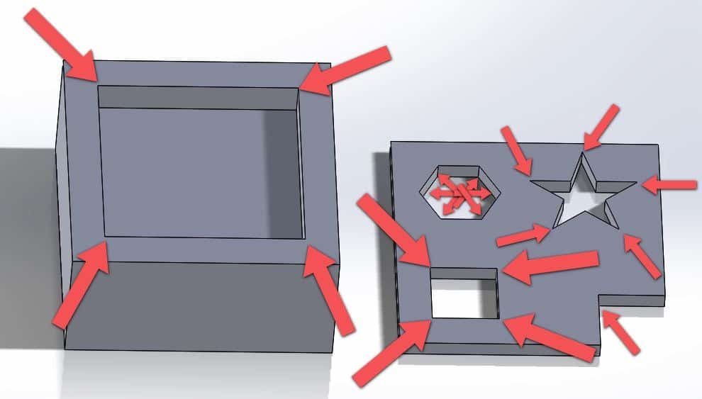
What is a Square Inside Corner?
These dreaded square inside corners are anywhere that a round cutting tool will have a hard time reaching. Let me illustrate:
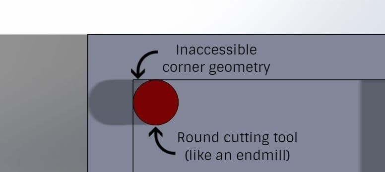
Since the tool needs to rotate in order to cut, there is no way for one of these styles of tool to make a sharp inside corner.
Alternative Styles of Corners
While these square corners look great on paper (or a computer screen), they’re often simply not a good way to make machined components. Let’s look at some common alternatives.
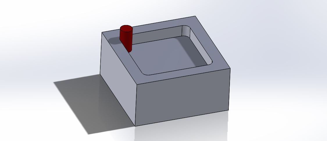
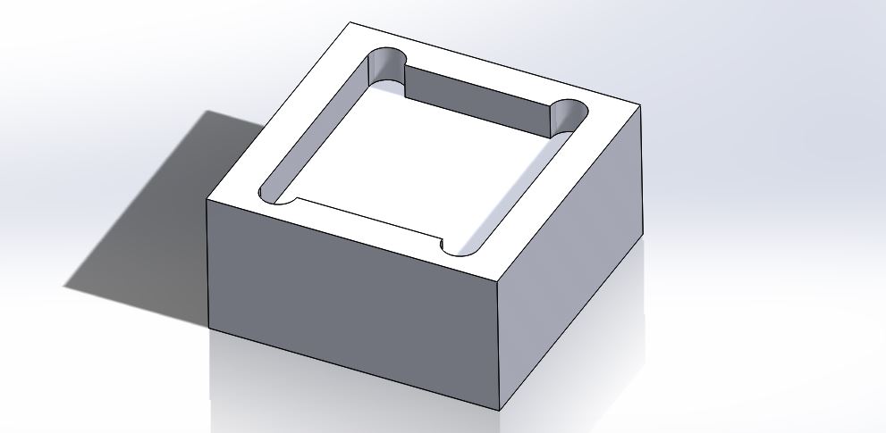
Radiused Corner
For many applications, (approximately 99.735% of the time, actually) you can simply allow for a radius to be in the corner. Typically this isn’t a big deal, so unless there is a very specific reason as to why having a normal radius is impossible, just go this route.
Here’s an example of what this would look like, using the example of a pocket:
This is the way that the aerospace industry has been designing components for centuries.
Ok, maybe not centuries, but you get the idea.
A radius on internal corners is a good thing.
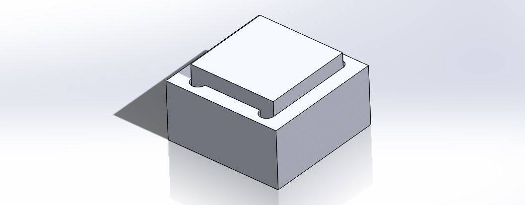
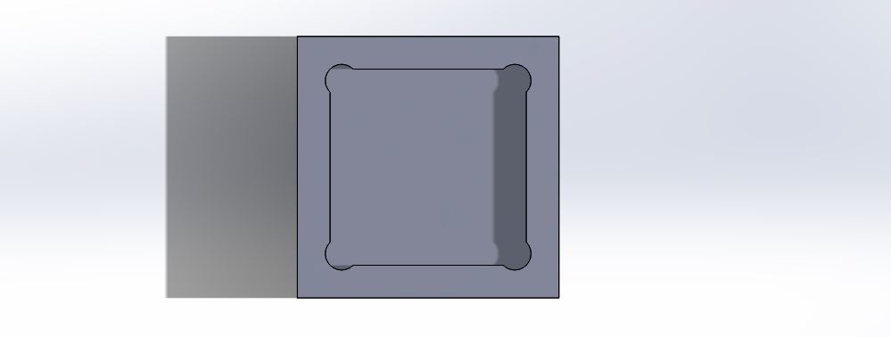
Ok, so let’s say that simply putting a radius on the inside corners won’t work for you. Maybe there’s a mating part that’s square and it needs to fit in that pocket that we were using as an example above.
There are a few ways around this. Either you can round the corners on that mating piece to make it fit, or you can make undercuts in those corners. Let’s take a look at some examples.
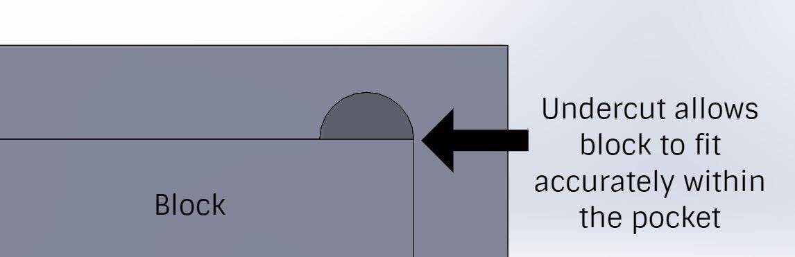
One-Sided Undercut
This is the easiest type of undercut for manual machines, since no extra calculations are required. All you need to do is cut half the diameter of the tool further in one axis. Here’s an example:
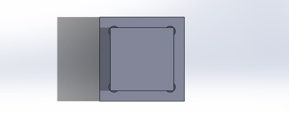
And here’s an example of what it looks like with a mated part:
Two-Sided Undercut
This is an undercut that balances the removed material on either side of the corner, and the result is an overall stronger corner. It takes a little bit more calculation for manual machines, but for CNC it’s extremely straightforward. This style is my go-to whenever it’s allowed.
Here’s a sketch that illustrates how to design the two sided undercut:

Now in these examples, there is no clearance. If the mating part has a broken edge, this isn’t a problem. If it’s a sharp edge, I like to add a bit of clearance on that corner undercut to make sure it will always cut cleanly. Something like 0.010″ on a 0.25″ radius undercut usually works perfectly fine.
Here’s a pro tip: If you’re wanting something CNC machined, make the radius slightly oversized from the intended tool diameter. What this does is reduce the contact area of the cutter against the finished part geometry, and will result in a better surface finish.
I’ll usually try to give an extra 0.010″-0.015″ extra clearance for most tools. So, for example, if I’m using a 0.250″ endmill, I’ll make my corner radii 0.135″ instead of 0.125″. If I’m using a 0.500″ endmill, I’ll make the rads 0.265″. It just works better.
My favorite way of designing this is to add the radius to match the exact cutter diameter, then offset the surface by the 0.010″ or 0.015″ – that way you get both your smooth, chatter-free surface finish and the extra corner clearance to make it work every time.
Using Smaller Cutting Tools
This is one option that often comes up in conversation. If you really need corner rads, how small you can make them?
The real question is how small they need to be. The smaller the rads, the more time and expense there will be in the process. Let’s go over some guidelines that can help you make this call.
What’s basically going on here is that the practical radius of the inside corner is heavily related to the length of the tool required to cut it. So if you need a deep pocket cut, you’ll need a long tool.
Really long, skinny tools just don’t have the rigidity to work that well in real life. If it’s at all possible to avoid them, please do so.

For a good reference, look up what endmills are standard length and which ones are extra length. Standard length endmills can be run with no problem whatsoever. Extra length endmills need to be run slower, and a good surface finish is more difficult the longer the tool gets.
As a rule of thumb, here are some comments on a few length to diameter (D) ratios:
| 2xD to 3xD | No problem whatsoever, use this whenever possible. |
| 3xD to 5xD | Extra length tooling needed for reach, but still doable. It just needs extra consideration. |
| 5xD to 10xD | The machinist will likely use your name as a curse word. Special tooling is generally required. |
| Over 10xD | At this point, you should be considering whether traditional machining alone is the best route, or whether other processes should be considered. This will start to get expensive quickly. |
Now these aren’t hard and fast rules, and some shops specialize in jobs that require long tools. But you’ll probably find that the majority of general machine shops will follow this trend.
Tools and Equipment for Sharp Internal Corners
There are actually a lot of tools and equipment out there that will give you sharp internal corners to varying extents, but they nearly all share something in common: they’re expensive.
Let’s go over them.
Broaches
A broach is a toothed tool that’s used to remove material. There are two kinds – linear and rotary.
Linear broaching is probably the most common of the two. It’s a typical way of making square through holes in thinner plates or keyways.
Even though the tools themselves can be expensive, they’re a great solution for production runs.
For linear broaches, the function is similar in concept to a band saw blade, except that each tooth is higher than the next. You can drill a hole in a plate, insert the broach, then use a machine (like an arbor press, hydraulic press or a broaching machine) to push the broach into the workpiece, with each tooth removing a small amount of material until the final geometry is reached.
I’m going to make use of videos to illustrate these manufacturing methods, since they will allow you to quickly wrap your head around how they work. I didn’t make these videos myself, and I apologise in advance for the awful music. You may want to mute your speakers.
Here’s what it looks like when you’re using a broaching tool with a press:
Here’s an example of a large broaching machine, which is generally only used for very large production runs:
There are different styles of linear broaches, too. Some attachments can be added to machines like a CNC lathe to cut internal keyways and other geometry. Here’s an example:
Rotary broaching is really cool – it’s a way of making internal polygon geometry, and it can be done extremely quickly in a CNC mill or lathe. It can also be done for making external geometry, such as splines and hexes.
Here’s an example of what this looks like:
The downside to rotary broaching is that the units themselves are very expensive, so they’re typically only practical for medium or high-volume production.
Even for linear broaching, any tool that needs to be custom-made can easily cost tens of thousands of dollars.
Generally, though, off-the-shelf broaches aren’t terribly expensive. Some shops will stock common sizes for regular work, such as keyway broaches.
Filing/Hand Work
This is more so appropriate for hobbyists. You can use a file to square up corners.
Obviously, it’ll be tricky to maintain any kind of accuracy with this method, but it’s possible. Some guys have old die filing machines, which speeds up the filing process, and makes it slightly more accurate.
Here’s a video to show you what this looks like:
Alternatively, you could use a pneumatic Dynafile to get it close-ish if the hole is large enough. There’s a 98.2% chance that it will end up a total hack job.
Some guys can do absolutely beautiful work this way, although they’re usually the old-timers and they’re a dying breed. It’s just not a modern way of doing it.
But, ultimately, if you’re the type that likes to grow your own cotton, spin your own thread and hand weave a new T-shirt, this might be right up your alley.
Shapers
These machines can usually be found in back corners of machine shops with older equipment.
A Shaper is a machine that uses a single-point cutting tool in a linear motion (no rotating) to slowly cut away material.
What’s nice about these machines is that the tooling for simpler shapes are generally fairly straightforward, and not really all that expensive. If you’re using a shaper for an internal spline, though, you’ll need professionally made cutters.
Here’s an example of one of these machines in action:
As you can see, they’re not terribly fast.
One thing that’s worth noting about these machines with linear feeds: you need to have relief at the end of the cut. Otherwise, the chips will have nowhere to go and things will break.
For most geometry, it’s common to add a groove or crosshole so that the chips can properly dislodge and clear out. Here’s an example:
Wire EDM
These are really cool machines, but they’re very mysterious to a lot of people. Not a lot of machinists have worked on them.
EDM stands for Electrical Discharge Machining. Basically, an electrode uses voltage to break down and desintegrate material, rather than using an actual “cutting” tool.
Essentially, you’re using electricity to erode the workpiece.
Here’s an explanation of how it works:
Technically, you won’t get true square corners – you’ll get a tiny radius that’s equal to the radius of the wire (plus a little extra for something called a spark gap). Typically this will be in the neighborhood of 0.005″-0.006″, although it can be smaller.
If that’s not acceptable for your application, it’s not uncommon to do a very small undercut like what’s common practice for endmills.
Wire EDMs do have their downsides, though. The cut needs to go straight through the part so that the wire can be held taut and cycle through the workpiece. A cool thing about wires, though, is that they can tilt – you can cut tapers and other interesting geometries with these machines.
Another con to this route is that these machines are very slow, especially when compared to CNC cutting tools. This means that wire EDM jobs have the potential of being pretty expensive.
A huge advantage, though, is that these machines are insanely precise, and can give a great surface finish.
Sinker or Ram EDM
This process has more names than you can shake a stick at.
Instead of using a wire as the electrode, a ram EDM uses a block of material (like graphite, copper, etc) to erode the material.
The cool thing with this is that you end up with the negative imprint of the electrode that you made. So, for example, you can machine half the part in a CNC mill, then use the ram EDM to reach what you couldn’t on the mill.
Here’s a video that explains the process:
The down side to this process is that you need to make an electrode, which will wear out quickly and need to be replaced. If you need something very precise, you may need to make a roughing and a finishing electrode. Ram EDM is also a very slow process, so it ain’t cheap.
Alternative Manufacturing Methods
It might be that the part you want to produce doesn’t need to be machined. Or maybe it could be made using a few different processes.
Here are some other manufacturing methods that might be useful.
Laser Cutters
If you have work that’s 2D and made out of sheet metal or thinner plate, laser cutting can be a great solution. It’s very economical, and there are laser cutting shops nearly everywhere.
You still won’t have perfect square corners, since the laser has a diameter and the kerf is a little larger than the laser, but usually this radius is so small that it’s negligible.
The main disadvantage to laser cutting is the surface finish and accuracy. While you can usually get features just that are +/- 0.005″ on something like a 1/4″ thick steel plate, you’ll find that the surface finish is considerably rougher than a machined surface.
Here’s a video:
Casting
Casting metal can be a great way of getting wonky shapes, but this can be quite the art to learn. Lots of guys can rig up a setup to cast metal in their back yard, but the results can be pretty wildly variable.
If you need something precision and you have a high volume of parts, die casting can be a really interesting solution.
That’s just one of the many ways of doing casting, though.
Different casting methods have different design constraints. For example, for casting processes that use hard moulds, draft angles need to be added in order for the parts to not shrink and become stuck in the molds.
For lower a lower cost method, sand casting might be practical. The main challenges with this method are getting a good surface finish and dimensional stability, since metal shrinks when it cools.
3D Printing or Metal AM
This is a rapidly growing technology, but the basic idea is to take the opposite approach to most traditional manufacturing methods.
Instead of taking a block of metal and whittling it away into a finished product, metal AM (additive manufacturing) takes raw metal (often in powder form) and fuses it together, like with a laser or electron beam.
It’s pretty cool stuff.
Where I work, we use the Direct Metal Laser Sintering process. It fuses metal powder layer by layer, and it’s really impressive to see what kind of geometry is possible.
Here’s a video that gives the basic idea of how it works:
Of course, there are still limitations (just like there is with anything).
For example, the surface finish out of the machine is generally pretty rough. Anything that needs to be highly precise or smooth will need to either be machined or postprocessed some other way.
It’s also an expensive process, so it’s often cost-prohibitive for simpler parts.
There are other metal AM technologies that aren’t as expensive, but not quite as high performance. Binder jetting is one of these technologies – it can fairly quickly make complex geometry (including square internal corners) but they material will be a blend of metals that aren’t the same as your typical billet.
Ultimately, square corners are a great thing to avoid whenever possible! All of these processes have pros and cons – until we reverse engineer the Star Trek Replicator, that is.
Do you have any questions? Or do you have a few tricks up your own sleeve on making square corners? Share them in the comments below!