G73 on a Fanuc mill is for fast peck drilling. Here’s an explanation on exactly what it does, how to program it, and when to use it.
Table of Contents
G73 Canned Cycle Motion
The main reason to use G73 is to break up long, stringy chips. This is common when using jobber drills or counterboring tools.
As the tool moves down and cuts the workpiece, the machine will quickly lift up slightly (usually .010-.020″) to break the chip, then continue cutting. The tool only moves a small amount during these retracts, so the G73 is not much slower than G81 straight drilling.
Here’s a video to illustrate this motion:
If you were to use the standard G81 straight drilling cycle, long chips could jam up your chip conveyor or tool changer. They can also nest around your tool and mar your workpiece, as well as prevent coolant from getting into the cut zone.
G73 Commands
These are the commands that can be used for the G73 canned cycle:
| X | The X axis position of the hole |
| Y | The Y axis position of the hole |
| Z | The final Z depth of the hole. This is in reference to the program origin when using absolute programming |
| R | The retract plane. The tool will rapid down to this Z height, and then feed to the final Z hole depth. In G98 mode, the tool will retract to the initial Z position before drilling. In G99 mode, the tool will retract to this R plane. |
| Q | Peck depth. This is how far the tool will go down before making the fast retract that will break up the chip. |
| P | Totally optional, and I rarely use it. This will make the machine dwell at the end of the hole. P1000 is equal to a dwell of 1 second. |
| F | Feedrate. When you’re milling in G95, it’s input in inches per minute. |
G73 Program Example
Let’s write out a program to drill the holes in this block:
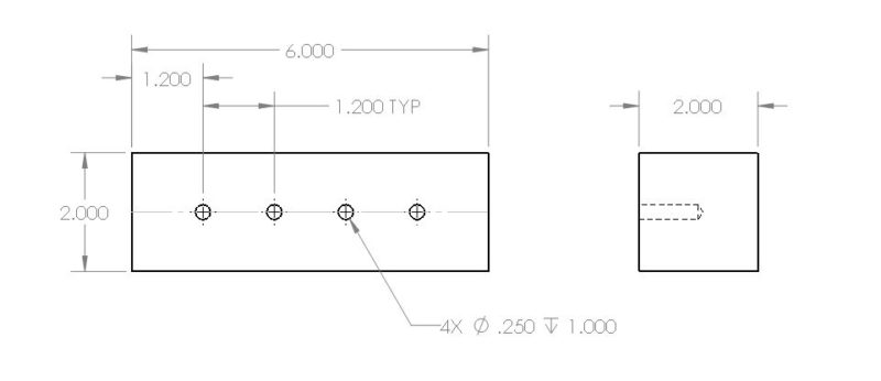
The material is 6061 aluminum, and we’ll use a regular old 1/4″ high speed steel jobber drill.
We’re going to assume that the facing, profile, and spotting are already done. We’ll just focus on the drilling.
So since this 1/4″ hole is only 1″ deep, G73 is the ideal canned cycle. It’ll break up the stringy chips so they don’t jam anything up. We probably don’t have to worry about things like getting coolant to the tool tip since the hole is so shallow.
Here’s how we could program this:
O1000
(BLOCK_DRILLING)
G00 G17 G40 G90 G20 (this is the safety line)
N10 ( OPERATION: DRILLING )
T01 M06 (0.250 HSS JOBBER DRILL) (this line calls the tool change)
G00 G54 X1.2 Y-1. S4000 M03 (calls the G54 work offset and moves the tool above the first hole, also turns on spindle at 4000 RPM)
G43 Z.125 H01 (picks up the tool height offset and brings the drill down to 0.125 above the workpiece)
M08 (coolant on)
G73 Z-1.0 R0.1 F16. Q.0625 (drills the first hole, peck depth is 0.0625, retract plane is 0.1 inches above workpiece, we’re cutting at 16 inches per minute, and going down to a Z depth of 1 inch)
X2.4 (drills the second hole)
X3.6 (third hole)
X4.8 (fourth)
G80 (cancels the canned cycle so that no more holes are drilled when you call out a new XY position)
G00 G91 G28 Z0.0 (home the Z axis to get the tool out of the way)
G00 G91 G28 Y0.0 (home the Y axis to bring the table forward so you can inspect your handiwork)
G90 (returns the machine to absolute positioning mode)
M30 (end program)
How to Choose a Peck Depth
This is much easier to determine compared to other cycles, like G83. This is because the peck happens so quickly. More frequent pecking doesn’t have nearly as much of an impact on overall cycle time as a full retract drilling cycle.
The main factor in determining the Q value for peck depth is the material and length of chips. Use a lower Q value for gummy materials that tend to make bird’s nests around the tool.
As a starting point, try a Q value of 1/4 of the tool’s diameter. So for a 1/4″ drill, a Q value of .0625 will generally give you nice, short chips that won’t tangle up your tool changer.
When you’re ready to run the program, just observe how the chips are coming out. It’ll vary tool to tool and material to material. If the chips are less than about 4″ long and aren’t wrapping around the tool at all, then you’ve hit the sweet spot.
Things to Watch For
The actual retract distance of the tool will generally be set by a parameter in the controller. Typically it’s a value between .010″ and .020″.
New machines should be able to perform great with a retract of .010″ before continuing the cut. The ballscrews aren’t worn out and everything is responsive. It’s the older, more tired ones that will need a bit more motion to make sure that the chips actually break. They just can’t reverse direction and jump back as quickly with such a small motion.
So if you notice that the chips aren’t really breaking cleanly as programmed, this could be something to check for. Look through your machine manual to find where this parameter is and increase the value.
Also keep in mind that not all materials need a chip breaker. For example, cast iron and brass chips will often break on their own with a straight G81 drill cycle.
At the end of the day, just play around with parameters and mess with it until it works. It’s what we all do.