When I built my first router in my dad’s garage, I was really excited to make all kinds of things with plastic and aluminum. I went to school for machining, and I worked in shops with some pretty high-end CNCs.
After the fourth snapped endmill, something dawned on me:
Routers are totally different animals.
Let me share what I’ve learned about how to cut aluminum with a CNC router.
Table of Contents
Lubrication
You’re going to want to use some kind of lubrication for aluminum. You can get by without anything for a short amount of time, but it’ll be riskier the longer you go without. If you’re planning on letting your router buzz away for 4 hours unattended, don’t expect your cutter to still be in one piece when you get back if it’s run dry.
There are a lot of websites and forums that say that oil mist is required for cutting aluminum.
It’s not.
It’s really not a bad idea, though. If you want to do the upgrade and have the resources to pull it off, I’d definitely recommend installing one. I use mine all the time for plastics and metals.
They’re not hard to set up. All you need is a kit, compressed air and a bit of oil. The whole package will cost you under $100 (assuming you have an air compressor), so if you use your router reasonably often it’s a really smart upgrade.
While it definitely is my preferred way to cut it, there are a few alternatives that also work great.
Probably the simplest is just hanging out while it’s cutting and giving it intermittent sprays of WD-40. It you’re like me, you’ve probably already got 6 or 7 half-full cans of the stuff on your shelves and in your toolboxes. No reason to overcomplicate this.
There is an area where this doesn’t work the best: if you have a router with a downwards exhaust. I mean like those big Porter-Cable types of wood routers that have lots of power. They’ll blow a ton of air all around the tool, without actually getting air to the tool. It can be pretty tricky to get a decent spray around that air blast.
Not impossible, though. You can use those little red extension tubes that come with the can to help get the oil right to the tool. It’s just a little annoying because the air will blow away any oil that’s more than an inch or two away from the tool so you have to monitor it closely. I have a water-cooled spindle so it’s no problem for me, but it depends on your setup.
Another great option is to use a cutting wax. However, this works better in some application more so than others.
Cutting wax can be smeared all over the top surface of where you want to cut, and it’s great because it sticks on – even a downward exhaust won’t take it off.
This works amazing for work that will be done at a single or shallow Z depth, like when you’re working with sheet metal or engraving. If you’re doing deeper work with lots of Z levels, wax will do a better job of lubricating just the first pass.
To get it to lubricate further down, you need to reapply it in that recently-cut channel. Not the end of the world, but I always like to let machines run without me babysitting them.
Small Tools
For the heavy duty CNC milling machines at work, my go-to was a 1″ diameter solid carbide roughing endmill for tough alloy steels.
Obviously, that wasn’t going to work for a little hobby router.
Small tools work much better – but even still you need to know what kind of tool to use for aluminum. They’re different from plastic-cutting tools.
Here are the basic qualities you want out of a cutting tool for aluminum:
- Great chip clearance – aluminum is gummy stuff that loves to plug up cutters, so the best way to handle it is with cutters with a lot of space between the flutes for the material to clear out while cutting.
- Strong tool – aluminum isn’t a hard metal, but you can still easily break a cutter on it. The 1 flute endmills that are popular for plastics often aren’t strong enough for aluminum
- Smooth – since aluminum likes to friction weld itself on to cutters, it’s better for the surface finish of the cutter to be as smooth as possible to reduce the likelihood of something bad happening.
- Up-cutting (higher helix) – for plastics, it’s common to see down-cutting tools, or tools that have a downwards cutting pressure. Aluminum will just gum up if you use that. Straight-flute bits don’t work so great either – the whalloping impact as it cuts just makes for a nasty looking cut. The best one to use is a cutter with a solid angle on the flutes that will lift the chips up and away from the cutter and gives a smoother shear to the cut.
This is why I really like using carbide 2 or 3-flute endmills whenever possible; they have enough chip clearance to reduce the chance of the aluminum welding itself to the cutter through friction, but they’re much stronger than the 1 flute endmills. Your cuts will look cleaner, and the tool won’t break as easily.
Typically I’ll use a 1/4″ endmill since my machine can handle it well; I’ve done a few mods to make it a bit more rigid. If your machine is really little, you might want to use a 1/8″ endmill for cutting profiles.
Here’s a link to the 1/4″ endmill for aluminum. If you have a decently rigid home build, it should work fine. If you have a small machine, then you should start off by trying a 3/16″ or 1/8″ cutter. Those all have a 1/4″ shank so you don’t need to change your collet when swapping them.
Another factor is your RPM – larger tools need a lower RPM, so if you can get down to 15,000 RPM then the 1/4″ endmill will generally work well. If you can’t go less than 25,000 or 30,000 RPM then you might not want to use anything more than a 1/8″ or 3/16″ cutter.
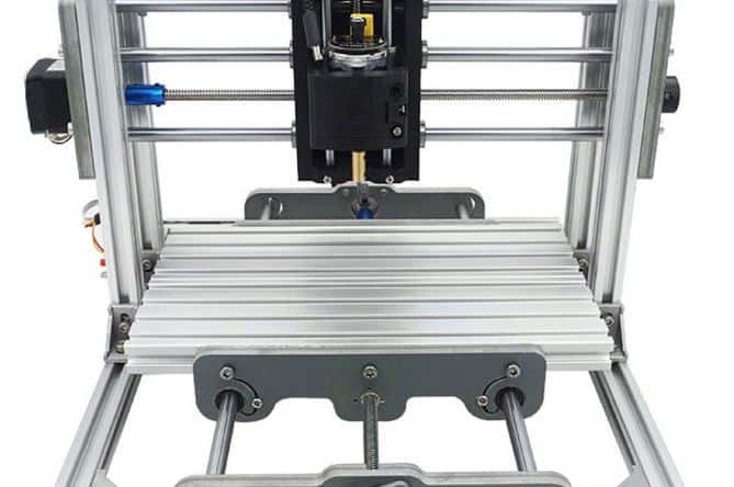
Rigidity
The cutting parameters and quality of cut will depend a lot on how rigid your machine is. Small hobby routers and the big $100k machines are very different.
Aluminum needs a lot more rigidity that wood or plastic. If you push it too fast, you might actually be able to see your machine flex under the load, if not rattle loose.
Here are some tips for dealing with a machine that’s not too rigid:
- Use stubby tools. The longer the bit, the more leverage the workpiece has. When you’re buying bits, keep an eye out for “stub end” endmills. Keep them nice and short in the collet.
- Use a really small depth of cut. For my first machine (before I did a bunch of upgrades to make it more rigid) I could only go down about 0.010″ per pass in the Z when cutting aluminum. The nice thing about using small Z depths is that you can usually crank the feed rate.
- Consider taking measures to boost your machine rigidity. I used aircraft cable and steel pulleys to add some tension to the bridge (mostly ‘cuz I’m cheap). It worked, though – that really made my machine less prone to issues with flexing and vibration. Some people have added extra ball screws and bearings to make their machine more rigid.
I’ve always found that the more you do to deal with rigidity issues, the better the job will go.
Speeds and Feeds
This is usually the first question asked, but the least likely to get a straight answer.
CNC mills and lathes are generally very predictable in how rigid they are. That’s why we can calculate optimal speeds and feeds without too much testing.
Not so with routers. They’re way more finicky, and since each machine is a bit different, it’s almost impossible to know beforehand what the “sweet spot” is unless you know your machine well. A homemade hobby router will be very different from a large router that’s professionally built for aerospace composites.
Either way, there are a few starting points that might work for you.
The textbook cutting speed for aluminum using a carbide tool is about 1,500 surface feet per minute at the high end, and 1,000 at the lower end. That’s not to say that you can’t spin it slower – you definitely can. But usually you don’t want to go faster than that.
So here’s how that translates to endmill RPM:
| 1/4″ carbide endmill | 24,000 RPM max, 16,000 RPM ideal |
| 3/16″ carbide endmill | 32,000 RPM max, 21,000 RPM ideal |
| 1/8″ carbide endmill | 48,000 RPM max, 32,000 RPM ideal |
| 1/16″ carbide endmill | 96,000 RPM max, 64,000 RPM ideal |
Now it’s pretty unlikely that you have a 96,000 RPM machine, but this should give you an idea of how cutter diameter affects RPM. If your minimum speed is 30k RPM, then you might want to shy away from 1/4″ endmills for aluminum in favor of something 3/16″ or 1/8″.
Some say that to reduce the “required” RPM, you need to use a HSS cutter. This is incorrect.
You do not need to run carbide at a minimum RPM.
Usually where people get confused is either one of two possibilities:
1) The machining handbook recommends a minimum RPM, so some people assume that the tool needs to be run at that RPM. That’s not what it means. It just means that you’re not achieving maximum efficiency for the tool. Not a big deal.
2) Some cutters do need a minimum RPM to properly use their features. For example, you need to run some coated endmills at a minimum RPM to “activate” their coatings. You will not likely be entering this arena of high performance machining with a router.
Basically, low spindle speeds are not a good reason to switch to HSS cutters. The only time that this makes sense is if you’re just starting out and you’re afraid of breaking a tool – Carbide is more expensive, but they work better and last significantly longer.
HSS is cheap but not really all that great. That’s why you usually see a lot of HSS in high schools – when the students mess something up, it doesn’t cost the school as much (they’ll break the tools before they get a chance to wear), and nobody really cares how fast their cycle time is.
Now for feedrates: This is a bit of a juggle with your Z depth of cut and XY stepover.
In general, you’d want to keep your chips small – something like 0.001″ per tooth for a 1/4″ endmill, and less than half that for a 1/8″ endmill.
So here are some possible starting points:
| 1/4″ carbide endmill, 2 flutes | 16,000 RPM | 32 inches per minute |
| 3/16″ carbide endmill, 2 flutes | 21,000 RPM | 21 inches per minute |
| 1/8″ carbide endmill, 2 flutes | 30,000 RPM | 18 inches per minute |
| 1/16″ carbide endmill, 2 flutes | 30,000 RPM | 10 inches per minute |
This may or may not work. It’ll totally depend on how good your machine is. If your machine is home-made and reminiscent of a wet noodle, you might want to cut those feed rates down by half. If it’s a $100k machine, you could probably double it if you want to push it.
For Z depth of cut, just test it. This will be a balance of machine rigidity vs tool size.
For a 1/4″ tool on a rinky dink machine, try starting of at a depth of 0.010″ and go up in 0.010″ increments. For the same tool on a solid machine, try starting at 0.050″ and going up in increments of 0.025″. Listen for when the machine seems to be under load, or when the cut starts to look ugly.
Here’s a little chart that will help you identify what the “sweet spot” is:
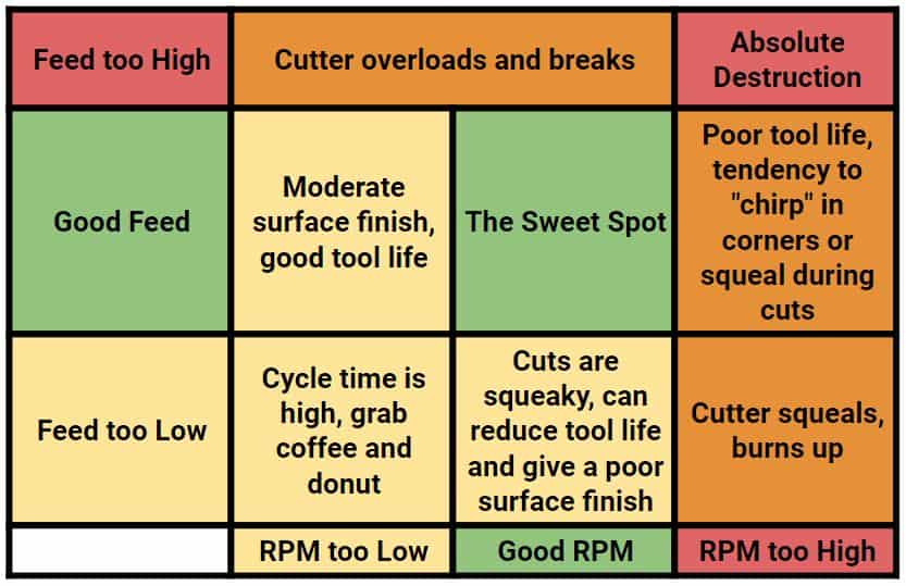
Honestly, you’re just going to need to play with it. That chart should give you an idea of what to look for to adjust the feeds and speeds to something that suits your machine.
Don’t get too worked up about this. If your router is fixed RPM (or very limited) then just adjust based on feed rate and depth of cut. It ain’t rocket science, just make it work.
Cutting Strategies
Toolpaths are actually pretty important for routing aluminum. Here are some tips.
Avoid plunging down into the metal whenever possible. Some tools are better designed for this that others, but it’s generally best avoided entirely. Unless you’re dealing with very thin sheet metal, that is. Then it’s not a big deal.
If possible, get to your Z cut level off the workpiece, and then start cutting. That’s not always possible, though. Sometimes you need to get the tool in from the middle of a thick sheet.
If it’s heavy aluminum, try not to just jam the tool straight down. What works way better is a ramping motion to get down to the required Z depth for the cut.
Generally, there are two common ways of achieving this: A ramp-on-shape type of engagement, or helical interpolation.
For a ramp on shape motion (some CAM software might call it something different) you’ll trace the profile that you’re wanting to cut while the tool slowly descends. It’s typically something like a zigzag motion. For most CAM software, it’s just a matter of checking a box and punching in your ramp angle. I usually go with something around two degrees.
For helical interpolation, you’re just making a spiral instead of a zigzag. This works well for holes, or when you’re making a pocket.
If you really have no choice and you have to plunge straight into the material, cut your feed rate waaaay down. Like if you’re running the profile cuts at 20 inches per minute, turn the plunge feed rate down to 4. Even then, pay close attention to see how it goes.
When disengaging from the workpiece (like when the profile is cut and now it’s time to get the tool out of there) a straight retract usually works fine. The only problem that’s common is to have a notch on the part profile where the tool retracted.
This is because the tool is no longer under cutting pressure to stabilize it, and the vibration and runout cause the tool to make a slight gouge.
To counteract this, use an “arc-off” motion. Basically, instead of just having the tool stop on the part profile, add an extra little arc movement in the XY that will get the tool away from the finished geometry when it’s no longer under cutting pressure and free to leave a mark.
Over time, there will be dozens of tips and tricks that you’ll pick up. This should be enough information to get you started with some pretty cool projects.
Have you done anything interesting with your router? Do you have some tips to add? Share them in the comments!